Page 1 of 1
Source of correct 90/6 wiring diagrams?
Posted: Fri Jul 18, 2025 3:53 pm
by focusrsh
I'm working on a friend's 1974 90/6. I have the Clymer "500-1000cc twins" book. It has a schematic for a 1974 R90s. It might be the same for a 90/6, but I'm not sure. I've looked on the internet for a wiring diagram and found some, but they all are all different.
Anyone have a source they trust?
Re: Source of correct 90/6 wiring diagrams?
Posted: Fri Jul 18, 2025 3:57 pm
by Kurt in S.A.
I would think that the S and the /6 diagrams are more or less the same. Another '74 diagram is here, though it says it's "Euro".
https://bmwmotorcycletech.info/schematic-1974-Euro.pdf
What are you trying to do or figure out?
Kurt
Re: Source of correct 90/6 wiring diagrams?
Posted: Fri Jul 18, 2025 11:26 pm
by focusrsh
Thanks!
together with the others I've found, that will help confirm
As to why, I'm replacing the starter relay,
The electrical engineer in me wants to understand why there are all these wires not related to the starter button, or relay operation, connected to the relay. (Like the one running to the horn!) Apparently, any tab on the relay was free game to use if it had the same power bus. Also, when I work on the electricals of any bike, I always "buzz" the connections and look for resistance anomalies.
Re: Source of correct 90/6 wiring diagrams?
Posted: Sat Jul 19, 2025 9:02 am
by Rob Frankham
focusrsh wrote: ↑Fri Jul 18, 2025 11:26 pm
Thanks!
together with the others I've found, that will help confirm
As to why, I'm replacing the starter relay,
The electrical engineer in me wants to understand why there are all these wires not related to the starter button, or relay operation, connected to the relay. (Like the one running to the horn!) Apparently, any tab on the relay was free game to use if it had the same power bus. Also, when I work on the electricals of any bike, I always "buzz" the connections and look for resistance anomalies.
The starter wiring relay on the early /6 models was a 'legacy' thing. The /5 models use a different relay setup that includes a safety lock out actually installed inside the starter relay. This senses whether the engine is running by monitoring the alternator output and prevents the actuation of the starter if there is any output. This was deleted with the /6 but the wiring in the loom wasn't changed... not sure why, maybe it was to do with backward compatibility or possibly there were thoughts of re-instating the lock out at a later date and that never happened... or just possibly it was simply so they could use the same loom. by the '75 /6 models the relay had been replaced with a more generic type and the blue alternator connection was diverted away from the relay.
Less explicable is the routing of the main power feed from battery to ignition switch through the relay. The connection is not interupted. Yes you have to take power into the relay but, as far as I've ever been able to see, there's no reason to break the lead and have two connections there. It's perfectly acceptable to connect the two high current red leads together and run a secondary lead from the joint, direct to the relay. This reduces by two the number of high current connectors in the line, reduces the amount of corrosion at the connector and means that a generic class a relay can be used (for a big reduction in cost). This is exactly what BMW did on models post 1984.
Hanging the horn and rear stop light connections on the relay is simply a way of connecting into the fused 12v power bus at a convenient point.. no downside really. There's little consistency through the models... the /5 bike horns drew there power from inside the headlamp... later /6 models have the horns connected to earth and positive to the horn button. later models differ again.
Rob
Re: Source of correct 90/6 wiring diagrams?
Posted: Sat Jul 19, 2025 8:10 pm
by Airbear
I find dense schematics impossible to follow due to my poor eyesight. Since I am an Autocad abuser I drew up a wiring 'map' that made sense to me when I was trying to get my head around the mysteries of my bike's electrical system. It is derived from the coloured diagram in the Haynes manual.
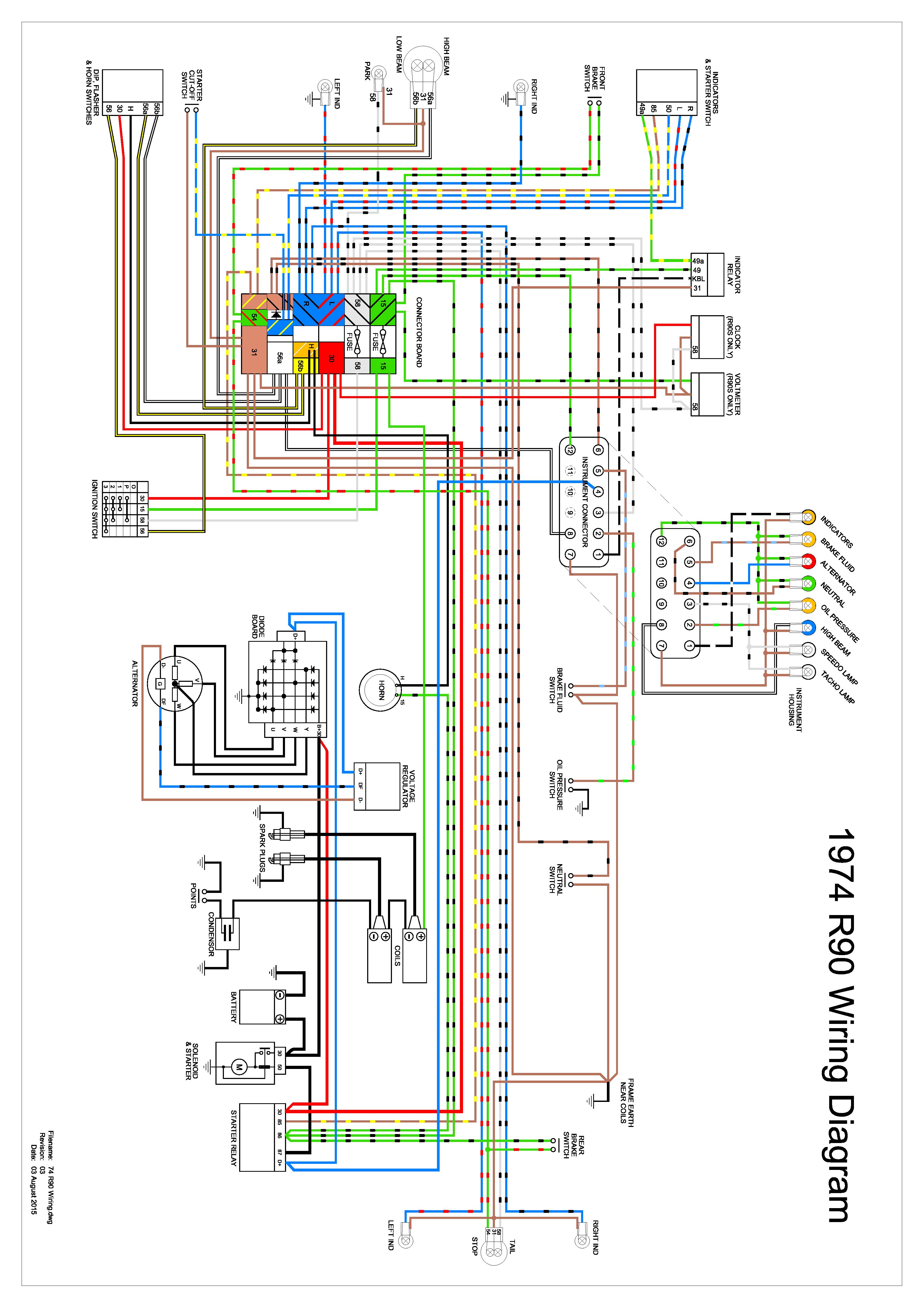
- 74 R90 Wiring Rev3.jpg (1.25 MiB) Viewed 46449 times
And here's my 'map' for the '74 instrument pod:
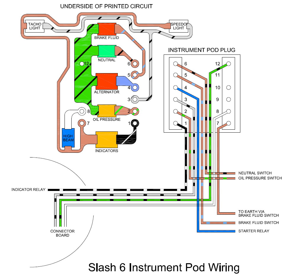
- SLASH SIX POD 150727.jpg (148.34 KiB) Viewed 46449 times
I hope these will be useful to you.
Re: Source of correct 90/6 wiring diagrams?
Posted: Sun Jul 20, 2025 11:03 pm
by SteveD
They're fantastic Charlie!
Re: Source of correct 90/6 wiring diagrams?
Posted: Mon Jul 21, 2025 10:52 am
by Rob Frankham
No one appears to have said it yet but the wiring on Euro spec /6 machines (and many others) is different to that used on US spec /6 machines. Also '74/'75 machines are VERY different to '75 and '76 machines. Not sure where you're based but unless you know what you're looking for, you have a 1 in 4 chance of a random /6 diagram being right for your bike.
Be a bit wary of the diagrams published for airheads in any case. Very few of them are completely accurate... and that includes those produced by BMW themselves. For example in the diagram above:
1) there are two blue wires shown sharing a single terminal in the starter relay. As you are aware, each of the wires , has in fact got it's own terminal. Makes no difference electrically but it's enough to cause confusion if you're not sure what's going on.
2) The wire from the ignition switch (or lights on/off switch where fitted) to the light dip switch is shown as solid yellow. BMW and other diagrams all show this is yellow with a white tracer (except Clymer which shows it as green at one end and yellow/white at the other

).
When working on airhead electrics, a basic knowledge of electrickery is very useful. As an electrical engineer, you should be fine as long as you treat (all) wiring diagrams with a small pinch of salt!
Good luck.
Rob
Re: Source of correct 90/6 wiring diagrams?
Posted: Mon Jul 21, 2025 11:58 am
by dwerbil
On my gallery, here's a online owner's manual for the R90/6.....
https://pbase.com/dwerbil/bmw_motorcycle_r90s_manual
Re: Source of correct 90/6 wiring diagrams?
Posted: Mon Jul 21, 2025 12:14 pm
by Rob Frankham
Useful but bear in mind that seems to be the manual for the '75/76' models.
If it's useful, I do have a pdf version of the '74 model user manual and also the repair manual...
Rob